Wednesday, 26 March 2014

At last

After months of work the Moblayne R/H is in place, albeit not totally as its still just sitting there, & with some minor adjustments to be done to the internal lighting, that will stay as is for the time being, the only other things needed for completion is smoke shute covers, & external lights to the outside of the shed, 5 in total.

In the end I had to do some timber removals as I really felt that having the roof battons served no useful benefit anyway, so they came off.


Down  approach to Moyblayne approximate location of the distant signal, just past garage shown on previous photo.


There are some lights too bright which will be fixed, although they look brighter in photo's rather than real life although I will try to bring the levels down.
Using cut up pieces of Styrofoam boxes to form low embankment from road to trackside. Short cut out is road access into depot Home signal to be located just past the crossing.


The above 3 pics show my first real attempts at clouds, while generally happy with the result the large on the left is not to my liking so an attempt will be made to alter it. The work on the clouds has helped to try & cover some problems previously mentioned with the backdrop which has been primarily caused by the active clay region we live in, dry weather cracks appear, wet & the cracks close up & now they push together forming ridges, nothing really can be done, so its live with it & try some different things to cover up the imperfections.

Primary through main road is in place the next steps will include road base to go in place with dirt. With this section on the move now, the finishing of the pub along with other buildings  will take place.
 
Last but certainly not least.   One item that I had been eagerly waiting for was the platform for the Coxes Gully goods shed, it was a real pleasure to receive if from Rod Kelly on Monday just gone, along with his wheel painting device & another water tank stand, the main truss part of the stand was cut out that night, & now ready for assembling, this leaves one more stand that is needed.

I say a real pleasure to receive the platform as I looked over it, & while the detail is superb, the actual assembling of it by Rod is absolutely top rate, a real pro's work indeed. 

As I looked at it & put the Ian Lyndsay building on it, I thought that it actually needs to be eventually situated elsewhere & it will end up in the Moblayne goods yard, I will scratch build a G1b goods shed for Coxes as it would be a more suitable size for this location.

A real appreciation of work indeed & many thanks Rod.

 
The timber platform with Ian lyndsay shed on it. The 2 MRC's are the latest run from TOR. Still the same body but the additional items of detail improves the look, the worst is still the timbers which are a bit too heavy & deep, also the paints pretty heavily gloss. 


The worst aspect I find with weathering models factory painted is getting chalks & powders to stick, I have a steel Scratch brush from Walthers a $4.95 investment that I love, the first photo shows one side with original paint & condition, above photo, shows the platform from Harlow graphics also my weathering of the other side of the MRC after using the scratch brush to take back the paint, & apply the chalks
An OTM latest run LLV, sits next to the MRC, this has been weathered slightly with the scratch brush, & some chalks on the scratch brush, bogies are painted using Sonja's Nimbus grey as undercoat & chalks on top.
 
I have found the MRC wheels to be slightly too thick, & bind on my 1:40 grade with 28" radius curves that also has some super elevation on them, replacing the wheels with 100 wheels from TOR, improves them no end. In the AMRM review mention was made about the wheels supplied with the models being not what was ordered, sadly some more issues with China factories.  I could not work out why the binding too place until I did a back to back measurement of the actual wheel, which revealed the ones on my 2 models were closer to 0.114 than 0.110, shows how much affect a near 1mm oversize of 2 wheels has an impact, as the models ran freely with the wrongly supplied wheels on straight track & likely larger radius curves but with the narrower wheels they run as well as any other wagon on my layout.

Sunday, 23 February 2014

Old vses new

During idle/wait times with the RH I have taken the chance to look at some other areas that are needed to be done, one of those is with my Rolling stock.  While I have a few kits, much or really most of my R/S are RTR models that have been collected over the years, what is very obvious is the change in the overall levels of detail on them, I could use the term quality but that is a term that I would prefer to leave alone as every person has their own view on what we receive these days, & being perfectly honest I believe a lot of them, leave a bit to be desired, some more so than others.

My chief desire is to have a layout operating that is representing an era in the NSWGR, its not a replica of any place or the like, & while I admit to my little areas of being pedantic, I am a bit forgiving in others, allowing for a bit more fudging in them. So in one of the recent idle times I was going through my box of RTR goods rolling stock & the smallish collection of some S & K trucks, with a couple of exceptions they are RTR versions of the old Austrains brand, now belonging to TOR.

Sometime soon the new Ultimate S truck from Austrains, is supposed to arrive &, I wonder what this model will actually be like compared to the others & at what price? The models I have in kit form are old Bergs models, dating from the 60's with a price tag of $6.50 on the bag, a Callipari model from around the same time with the cost IIRC of around the same price.  I actually shudder when I look at what we got back then, the Bergs bag comprised of 4 sides & a floor, which I never got to fit without cutting the sides down in length, & was baffled at the ends with some weird casting, which I supposed was to replicate the fixture for a hook coupling, the sole bars never seemed to sit square, & these days only bits remain of them, A K truck has the same coupler set up & the same problem with the sole bars & W iron parts that are bowed in one end & out the other. Now $6.50 was not cheap back then, especially as there were couplers & wheels to buy, & that was the same with the Callipari version, although later some ordinary plastic wheel sets came with them.

At least those went together well, & 2 still remain. The Bergs K truck has an old Urethane water tank in it & the side doors removed to be for filling lineside fettlers tanks, how that can happen is beyond me, owing to the contortioned W irons, & finding wheels to sit in them.

The 2 S truck kits along with the Austrains RTR are each of the same type, of which I understand there were a couple of different type S trucks were in service, that basically had different sides/doors to them, I guess I am hoping that the Ultimates will come out as one that is of the different door design than those already on the market. A reference in last years AMRM mentions TOR are rerunning the old Austrains types again, but we wait & see what mods are done to them when they arrive.

The thing is though, if these new releases, that is the TOR Rerun, & Ultimate are the same as those already done, I wonder at what value or price point they will be at, & are they going to be worthy replacements or additions to the old kits & RTR models?  In the interlude times with the Round House, I found I had 22 of the Austrains K trucks, getting them out, the glaring issues with them is the side doors with the ultra sharp & pronounced diamonds on them, the blob that is the hand brake casting, along with the thick side walls, & no internal wall detail.

Looking at the RTR S trucks the same thing shows up with them, although the side walls lack internal detail they are actually slightly thinner than the Callipari kits, whereas the Bergs kit is quite thin & brittle, ok they are now around 55+ years old so what do we expect?  I guess if one had the money & the ultimate turns out simply, well the ultimate I could stick them on ebay & hope they are worth something, or try to fix them up, & the same applies with the K.

The hardest part with both of them is the inner detail, but as most general goods trains even in the 60's had loading of some kind in both directions in these wagons, making loads or covering them with tarps can fix that problem, the hand brake can be replaced with some commercial products that will lift them ok.  Spoked wheels can be added to backdate them, & weathering helps on them as well.

The K truck is another matter, especially with the thick gunwale, & sharp diamond pattern to the doors. With only 22 in my current possession, I found one that I had tried working on some 10 years ago, a crude attempt to thin down the sides, looking at that work, I could see the potential in it, likewise the problem with the diamond pressed doors. 

Measuring the normal walls at the gunwale section the Austrains K trucks measured 2,37mm thick, measuring the Bergs Kit walls at the same point revealed them to be 1.4mm thick, near enough to 1mm thinner, a lot in a way to try & reduce the sides by.  However, I decided to try & see what I could do with a couple of them & how much I could reduce the sides by, in order to improve the look of them.

Using a sliding box cutter that has the large blades, similar in size to the old Stanley knifes. Sliding out the end of the cutter to a point where I had only enough of the blade sticking out to scrape the sides far enough down but to prevent it from touching the floor which has timber detail, I progressed to tediously scrap away at the sides & see how much I could take away.

The more I took off the more I could feel the side flexing in as I had to hold the wagon tight, with some caution I got the side down at the gunwale position to 1.67 mm. This I considered was far enough to go, especially with the flex & needing to do the other side as well. When scraping away I did so at an angle, meaning the lower part of the side was not touched & the sides actually are angled from about 2mm off the floor to the top of the gunwale.

I then tried the ends, but found the brass grab wires were set into the ends on both sides fairly deep, which meant little thickness removed but the blade section wrecked, leave well enough alone.  The next item was the diamond pressed sides, well external anyway.  The primary problem I found with these was how sharp the ridges of the diamonds actually were, which I thought was the primary issue, a comparison to the same pressings on a Callipari HGM wagon confirmed that opinion.

What I then did was another ultra simple mod, using a curved blade scalpel, I scraped along the top edges in an attempt to just take the edges off. This worked on some but did not seem to work on others, as well, so with them I used a flat ended Stanley hobby file to lightly file the tip ends off.  This worked quite ok & I was happy with the result.

As these models had been weathered pretty badly by me in the past, & found that the paint I had used, (whatever it was) was fairly thick & left a sheen on the models, which like an unpainted new model showed the diamond ridges very prominently, a couple of them however had been weathered differently & were quite gritty, how that was done I have no idea but certainly the diamond tips were not as bad.

Some photo's showing the K wagons both before & after the work to thin down the sides of the K truck to compare, with the weathering they have come up reasonably well, at least for me.
 Above showing the Austrains K trucks with old weathering but still showing the sharpness of the Diamond on the doors.

 Original K truck looking from the top showing the old thick gunwale of 2.37mm.

 Modified K wagons, showing new weathering, with the diamond sides after the edges were taken off.


Lastly looking from the top showing the thinned gunwale of 1.87mm thick.
 
These two simple jobs I believe makes the wagon a lot more appealing, sure it still is lacking but, even on my layout its hard pressed to notice a fully detailed underneath of any models while they are stationary, let alone when passing in a train movement.

Tuesday, 11 February 2014

Movements

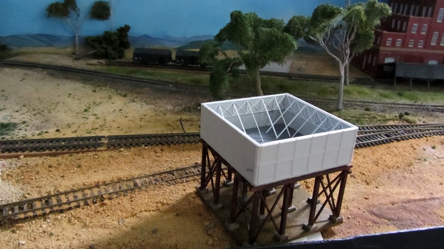
The waiting time for the RH windows allowed me to catch up on a couple of other jobs, including a water tank for the depot, I used a Casula tank with a timber Harlow graphics stand, I also decided that as I had time to partially detail the interior of the tank as per the articles in last years AMRM, a job that was a lot easier than I thought, however, I am still to do the wire trusses as I wait for the turnbuckles to come.

The timber stand was an easy enough building however removing the parts from the main block did create some problems, especially with the first one where I some small pieces pretty well disintegrated, but they glued back together pretty easily using PVA.

Following that problem I cut the remainder out from the board along the grain at each of the bearer ridges (can't think of the correct name) these ridges are connected by small nitches of timber which are quite hard even with a brand new blade. By removing as much of the timbers along the grain really gives a lot more room to work in to remove the parts. I spoke to Rod Kelly about this & he is going to work on the kit to make it easier to remove.

I thank Rod for the ease of talking to, & ever willingness to discuss issues with his products & make any required alterations.  I now am waiting on 3 more of his stands to complete my needs.


The big arrival was from Ian Phemister with the windows for the roundhouse last week, a quick nights cleaning & gluing the window panes into the frames, priming & then giving them an initial paint using Sonjas Acrylic Nimbus Grey which I use to get a nice flat base for my R/S & found excellent here as well.  I then used Acrylic soft pastels to weather the windows. A final coat is still to be done on the panes as RH windows were usually painted white but for some reason got pretty dirty over time.

The windows were then sat in place along the back wall of the RH, using blue tack to hold them roughly in place.


Once in position I was pleased to see that the rear wall & side measurements had come together pretty well, some minor adjustments only are needed with minimal gaps between windows, any filing that is needed will be done with some thin timber left over from the main construction.

The next step was to test fit the main RH building.


Again I am pretty happy with the result, although more work will be needed with this part of the construction, I am glad I have gone this route in building the whole structure, & thankfully there is not a lot of adjustments needed, overall I have to add around 1/2 inch to the rear or outer truss width on the R/H side, & about the same to the L/H mid section of the truss.

I wanted to build the RH as close to the plans as I could but the fine work of needing scale 3x2 timbers for the roof bearers really made me wonder at the sense of it, they were a right royal pain in the proverbials, but I persevered but really should have stopped & left them off.

The roof area is fairly extensive so fitting commercial model corrugated iron would have been an expensive proposition, as I have one of the Brunel corrugated iron tools I decided to try it out on the inner truss rear section. I found normal foil & the stuff sold by Brunel being not thick enough, also standard 20micron hairdressers foil the same. Delving into the pantry I found a roll of Woolworth Select heavy duty foil, labelled as caterers grade so decided to try that.

This proved much better & is stronger, but I would not use this method without any sort of support under it.  I measured & cut a strip of 1mm Styrene in two sections to cover the length of truss (the white that can be seen in the photo) & then glued using PVA the scribed foil over the top of the styrene, & left it for 24 hours to dry.

Using a very sharp knife I trimmed the foil off the edges, before gluing the whole strip to the rear of the Truss. Care really needs to be taken with using this sort of foil owing to it being quite thin & easy to tear, though the finished item does look quite good

There are basically now two major steps left before securing the RH to the base which is removable & will allow me to work on getting the rear wall, windows & trusses together properly. The iron roof will be done the same using 1mm styrene cut to fit the 8 stalls of the RH, after I finish working on the lighting.


Saturday, 18 January 2014


Ray Pilgrim, is noted for his modelling works & provides a lot of great information & challenges on his blog http://bylong.blogspot.com.au/. Its rare that there is a post that he puts up that does not have us putting our thinking caps on, especially in trying to create some new challenges, sometimes I think Ray has too much time on his hands & its not going to change now that he’s retired.

His latest post has an interesting read on the topic of train loads, for the modeller along with a spreadsheet he has created to assist in the working out of them for the modeller. As a result of his thread I tried to put a comment to help with some areas he raised, trouble was that I had to severely cut that back owing to the limits you are allowed in the amount of Characters in a comment.

With that I suggested that I put a post on my blog & he will also post it on his blog, this may help others as well in regard to this topic.  For non followers & followers of my blog, I refer you back to my post of 26/4/2013 that has some Teleprinter loads & other details on train composition to save repeating what was said there.

So, the aim of this thread is to look a bit more at the composition of train loads for the modeller in order to gain some better understanding of them & suggestions for working them out for the layout, as far as possible for prototypical working.

To begin with it really is not possible in the modelling scene to be totally prototypically correct, at least that’s my opinion if for no other reason than the constraints placed on us regarding layout space, & the many compromises needed to be made.  Looking at loads, who would have a big enough layout with say a long enough grade of 1:40 that would allow you to run a train that ran almost daily from Sydney to Port Waratah (PTW). That was 58 empty S trucks & Brake Van for a load of 486tons, which was hauled from Gosford by a garratt. The load is 170 under the full load for a garratt, but over the load for all other steam loco’s unless double headed. The problem is not as far as a model garratt may not have any problems pulling it but, no one that I know has layout that even comes close to the short Fassifern bank in distance wise, but also on an HO layout, it would look out of place & far too long.

Train loads on the railways were determined on what was deemed “through loads” that is for working over set distances, usually depot - depot or yard –yard, such as Enfield – Goulburn, Lithgow – Orange/Wellington, Enfield – BMD, & Enfield – Thirroul/Port Kembla. The through load is based on the steepest continual grade & the associated curvature/track conditions. The short south to Glbn the loads were based on 1:75 which was the primary grade between Enfield - Glbn, yet a very short section of 1:40 was had at Picton station to the Hume Hgwy bridge, also Exeter bank had 1:66.

The western line from Lithgow – Orange/Wellington (main line) was based primarily on the 1:66 grade at Locksley with rear end banker from Georges Plains to mileage 161-45 allowed that load to be hauled all the way to Orange without need to change engines.

While the actual tonnage bears the greatest consideration in regard to the grades, the other primary factor is the curvature of the track, this has the limiting affect on how many wagons are hauled, a long load of empties were taxed the engine just as much if not more than the actual load, the example of the 60 in length of S trucks, when compared to a load of petrol or wheat, shows a very short train by comparison. 7 loaded BWH & van = 463 tones, room for say a loaded S as cover truck then the load comes to 10 = 21 for 485 tones.

Also, just to confuse things, not all grades are the same, especially when it comes to the steeper grades of 1:40, a standard goods engine was allowed 360tons Enfield Hornsby, then 390 to BMD, for Tumulla, & IIRC Ardglen on the down was just 330tons, the sharper reverse curves were the reasons.

Looking at the goods load (in tons only) for other 1: 40 grades on the west, 36cl & the standard goods loco’s trains, we find the following. Down Orange – Borenore, 36 = 325, 50 = 385 UP Molong Nashdale 36 = 295, 50 = 385.  Light type garratt both directions 575, & heavy 600. Down; Blayney – Lyndhurst 36 = 275, 50 = 325.  Up Mandurama – Blayney 36 =310, 50 = 320. Comparing loads for grades as shown by the examples here shows differences in them all & each would have special conditions applying to these loads as shown in the WTT’s.

Single engine & double loads. As mentioned single loads were primarily based on both load & length, but when it comes to double headers, the load as well as the length becomes a becomes a balancing act, with the length often exceeding that of the single engine, which usually meant at best 5 extra S trucks could be taken on a double load, instead of 55 as per the Short south, it would become 60 in length, with heavy load & long length the double load in itself was quite taxing on a locomotive. The last consideration was the engine type, if both engines were of the same type, eg, freighters, or 36, 38, or a combination of the types, there was need to consider the lowest haulage speed of the engines & base the loads on that.

Freighters usually slogged at a max grade & load at around 8-10mph (1:40) closer to the 10 or a bit more, on 1:66 & greater depending on curves, a 36cl was usually around the 12-15mph, with a 38 around the 15-18mph, this can be seen in the running time sections of the applicable WTT. The mixed engines of passenger types were pretty easy, while a combo with a freighter often had a detrimental affect on the passenger engine as they could get slower than their loaded speed, meaning careful driving was needed, especially with 35 & 36cl as they could readily slip, & if you missed the tell tale exhaust talk warning you, it was possible for a bad slip pulling the fire on the pax engines, meaning big time trouble, bad on the pig, worse on the nanny.

75% loads.  These were common on the southern division in the pre exp goods train days, & generally confined to fruit & perishable expresses & stock trains, these were usually limited loads that ran to accelerated times, primarily on the grades though as the R/S & use of freighters limited the flat terrain speeds, balanced wheel engines excepted.

However, as freighters were withdrawn from the western division & replaced by 36cl, a lot of adjustments were needed. One being the tabling of all west bound through goods services to 75% loading & conditions. As single 36cl load on Tumulla was 285tons, but could take 485tons from Lithgow, doubling them with another pig banking at Tumulla load permission was given to run the through 900 ton double load assisted in the rear for 3x36cl, owing to the max length of 60 not being exceeded.

The 75% load was, as found in my comment on Rays blog, allowed for a standardised load to be applied to trains west of Lithgow, be that a single or double header  they being 485 tons single & 900tons double (the double load also was worked by heavy garratt) all taking the same length. This created an easy means for both train timetabling as well as making up of the loads at Lithgow or Wang as was the case for some trains especially for Cowra. As 36cl running times were generally applied the running up grades was faster than the slow full load slog of a freighter. These trains were simply called “three quarter runners”, & ran on accelerated timing.

The usual slowest speed that freighters were loaded for was app 8-10mph, the 36cl was 15mph, 38cl 18. In the above western sections, interesting that freighters hauled a heavier load than 48/49cl they were limited to 500 tons single over the same section & only 45 in length.

The other primary area to work the ¾ loads was on the south during the steam days, these were generally fruit, meat & other perishable trains that ran to the ¾, or accelerated running schedules, often the domain of the big engines.

How can the modeller work out what to do with obtaining a prototypical load?  In the end each individual will do his own thing, & work on more than likely what looks right in his eye’s which is not too bad of an idea at least to start with anyway.  For the modern era modeller, I have no idea of the way things work these days, loads length & even running times, so I will leave that to others.  I model as most would know a limited era time frame 1955 – 1957, a bit before my time but one that I know was not much different than the middish 60’s & pre the Mk2 44, & 48’s, except for big engines I worked on most steam in service in my chosen era.

The issue of load & lengths really only comes into play for the modeller who has grades on his layout, I have one section of 1:40 on a 28” radius curve facing up trains, thus it is the limiting load factor for my loco’s. The benefit of course is that it by its grade & curve is a limiting factor for modelling purposes, & each should look at his layout & any grades on it & make allowances for them.

The basic length is based on the humble S truck (those from the current Austrains releases are the same as an S truck for length purposes) all train loads & compositions (again see my previous blog post) were governed by that length, to complicate things, wagons like the K were 1.2 in length, some early bogie wagons were 2 while others such as the BD was 1.8, while later from the BDL onwards they were 2.3, a notable exception being the CG wagon that was only 1.7 in length.

For the modeller buying closed type vehicles such as BWH, & later wheat hoppers, along with other closed vans, its not really possible to work out a correct method for them, such as the difference mass, when empty to that when loaded.

The method that I have used to determine that situation is to simply take those wagons on down trains to be empty, while up trains are loaded. That means any loaded wheat train that consists of BWH only, will have 9 + Van, that equates to a train composition of 10 = 20 for 586 tons, which is the load for a light type garratt on 1:40 grade. That also comes close to what I have set my crossing loops to a general length of 2metres clearances, although 2 have another 200mm to play with, which helps with the garratt & big engines.

To simplify, the length situation, remembering that I model an earlier period, I make the K & RU & equivalent wagons as being 2 = 3 S wagons, for those modelling periods with the longer than 2 equivalent bogie wagons, a similar idea could be adopted such as 2 bogie wagons = 5 S trucks.

Short loads can be easily dressed up to give them the appearance of weight, I have some Aluminium square tube left over from my Sydney layout, very light & fit perfectly into S & K wagons, covered with tarps, means the train is loaded, so 8 tons becomes 23. With several of our RTR steam loco’s having pulling power problems, they struggle with any decent train length without some simple mods being done like adding weight, so they are great for the empties but not so for loaded, without the mods.

Some photo's here indicate the difference of loaded & unloaded trains working over 1:40 grades.  First loaded & where short trains can look ok behind steam & 1st generation diesels.  Even when empty, a model train does not have to be long & loaded to look right.


 Morriset. The mixed load of LCH/CCH, & loaded K wagons along with van brings the load to 598 tons, app 60 tons light, length is 23 =24.6
 

Same location, & same day, a 36 + 35cl have a full load of coal in LCH & CCH wagons, 16 CCH & 8 LCH + van 590 tons, length is 25=26, a full load for both engines.


 Tumulla. a 50 class is banked by a 36cl on a basically loaded mixed goods train working on the wagons & their loading the approx. load of the train is 20 wagons = 28 for app 615 tons, that would be the combined total tonnage allowed for a 36 & 50, 285 + 330 tons.


3811 being banked by 36cl a primarily loaded train 19 = 22.8 the tonnage of the train would be the same as the 36 & 50, as a 38 had the same load as the 50's


3630 on up goods from Cowra with a full load,10 wagons, 2 loaded BSV, 2 x loaded BWH, 2 empty RTC, K wagon & loaded MLE with tractor being transhipped + van 11=18.2 tonnage very close to the 310 ton load for the section.


 Empty bulks hauled by 3614 & banked by 3615 the loaded S is used as a match truck. 25 = 40.6 the tonnage would be around the 570 tons the load for two single 36cl.


An up goods near Nashdale hauled by 6015 32 = 47.  While much of the loading would be empty, with a couple more bogie RTC's & the van to come, it would have been close to the full load for a light garret 575 Tons
 
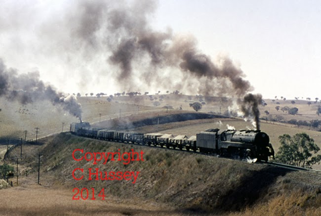
6011, on another general goods, with Molong in the background. Owing to it being an old slide & grainy, needing another scan done of it, its hard to pick the length of the train however given that the rear vehicles are empty flat wagons, with wool & other traffic including other empties, I would say the train would be very close to max length of 60 with a load of 575tons. Taken in 1966 entering into Spring with the drought broken.
 
 
Ourimbah in 1963. Here is where length & load greats a struggle the load would comprises petrol & a bitumen Tank wagon 2 loaded  S trucks & the stock wagons are likely loaded owing to train marshalling, the remainder are empty S & K wagons, load would be close to max tonnage & length for a single garratt.

Saturday, 21 December 2013

Shoe shuffle continues.

The roundhouse has been an almost constant stream of shoe shuffles some forward moves with a fair few back ones, thankfully though I think I have now reached the point where its more forward, less back but hopefully only forward movements from here.

Each phase of the construction has its moments, especially when one has never done a project as big as this before, so many new areas to learn, but I think the experience has overall been enjoyable.  The primary part of the roof along with all main trusses, & the inner or turntable end are now complete, awaiting the outer trusses with smoke schutes to be built & then attached.

The smoke schutes have been a challenge especially with getting the two trusses set together & supporting the schutes. Careful study of drawings & photo's gave me the positioning & basic measurements, along with how they were attached in the roundhouses.

With the schutes finished & trusses ready, the assembly became trial & error, especially trying to get the schute, supports in place & to hold together, in this area I could find no definitive drawing to give precise measurements & timber sizes, which meant a fair bit of licencing was needed. The first one took me a full day to get together without the edge box type frame.

The simple solution was to build the whole lot in small assemblies for strength rather than true scale fidelity

The above photo shows the truss with scale 6"x6" cross bars glued in place to keep a constant spacing.  I could find no detail or measurements as to the spacings along the back wall for the two trusses, the space measurements were there for the inside or middle parallel supports so for simplicity I decided on the same spacing along the whole of the truss.  .
The middle 6x6 is to attach the chimney part of the schute, one side glued to truss, the other to the chimney.

The next step was to glue the schute assembly to the truss.
 
 
Having tried to do this without the 3 extra spacings was a real nightmare, this time & using this process I was able to assemble all remaining 7 trusses together in an afternoon, while finishing off the original assembly ready for painting.

A finished assembly awaiting painting & then attaching to the main roof, I realised that the timber sizes were a bit large, so I set about cutting all the remaining 7 cage assemblies with finer timber, only the 4 vertical sections will remain as 6"x3" with the remainder being 4x3 inch.

While I have been as careful as possible with the PVA there is still some areas where the acrylic tube paints have not taken as well as I hoped.  So after one test of a finished truss I decided to try another paint tool I use occasionally & that is blackboard paint. This proved to be better than the tubes, as it went over any area of the waxy PVA paint & covered it without issue.

What I like about the acrylics & blackboard paint is their total flat matte appearance, no sign of a sheen even of the smallest amount. To me the two mediums along with the chalk pastels provide the dusty look that is more realistic than is able to be achieved with ordinary paints including model paints,


Thursday, 28 November 2013

A mammoth task, the 2 forward 3 back shoe shuffle.

The past month or so has certainly been exactly like the heading depicts.
Slowly improving following the surgery but confined to use a back brace until at least next March it means a lot of restrictions on movement & quite frustrating, but now having nothing besides a metal cage & 2 screws to hold my vertebrae in place, in order to allow the back to fuse itself I have a real desire to take time.

Thus the layout progresses at a slower rate than I would have liked, I am waiting on a friend to fix a TT for me, that will go in to Akuna for the day pick up/school train, he actually fixed my Antons 125 foot TT that I only supplied to him so he could use it for parts, but he found getting that fixed helped him with the small one. Now I have a TT I do not want, nor need, so maybe fleabay will get a listing for it.

Waiting for the TT to be fixed, provided me with the need to get stuck into the area cleared up for the main Loco depot at Moblayne, the first part was to get the backdrops in place & then to try & fix the areas slightly damaged during the hanging as well as the split from the long dry caused by our home being set on high active soil. With that fixed, well good enough for me, I set about doing the corner area behind the depot, with scenery, & connecting the painted backdrop to the photographic one.

Trusses as originally built & situated in place using blue tac. Nothing done on the backdrop & scenery.

The area was then finished with low lying scenery & some trees. Then the Roundhouse was taken up with some gusto. But with that start it soon became very much part of realising the task ahead, as well as what seemed to be the forward steps being out distanced by the backward ones. As the project proceeded, it was obvious that I had done things wrong in the first place, simply by putting the TT in place & thinking a simple task to build all other depot needs around it.

The theory, as well as practice would have worked had I had some more space than I have for the depot. At this point, I searched for Round House plans, & thanks to Ray Pilgrim for those he provided links to, also Ian Phemister for help, & Ray Love helped out with some drawings of his.

Early on I had built all the main trusses, & planned to have them set in place in the early stages, but it was apparent that a lot more planning & rearrangements were going to be needed.  The round angles had to be readjusted in order to ensure the track leads off the TT would be sufficiently apart for smooth & trouble free operation, The cutting of the pits, along with setting the angles, & back brick wall, was a large project of trial & error.
Ready for cutting the pits & foam cuttings for background scenery.


The pits were cut using a Trimming router, lent to me with a jig for the pits. As I am using Peco pits, with some modifications to build up the pit to be closer to the NSW pits, I had to adjust the widths using a single bit to cut them in place, what a messy & noisy job.  This work on cutting in the pits was done prior to the scenery being in place.
Basic scenery finished behind depot, the house & yard now awaits fences.

I had thought of different methods to secure the pits in place, ( I chose old faithful, clear Parfix roof & gutter sealant, holds everything in place firmly but allows for lifting if needed.)  & how to raise the Round house floor to the rail level. Initially I had looked at using some 3mm ply & build the whole RH & floor area separately & then move to the location, this was going ok until the ply decided it would fall off the layout top & break up into around 5 pieces.  I dismissed the idea of plastering the floor, & with more rulers & measuring I decided on cutting individual sections of 2mm Styrene to lock in around the pits.
 

The problem with this was that I had to do them in individual sections, a bit of a bummer at first but realised that the pit frame also raised the floor up by over near 4mm, & it left the styrene between the pits suspended, I used the cut out pieces from the sections where the pits were to show through to slide under the styrene, & that provided a firm & solid foundation.

This also led me to find the solution on fixing the truss support posts in position.


As prior to this my ideas that had seen me completely build all the trusses as well as glue to the main support posts, was seen as a bit of a folly, so another 3 steps back saw me remove the posts, but glue a length of 12x8 stripwood to the base of the posts at the correct distances for the two of them.  I glued the base to the pit cut out strips using Gel grip, cut outs in the styrene allowed the wooden sections to become secure, the styrene sat on top of the pit frames, & at the same level as the top of the 12x8, so a smooth floor was attained.


Various trusses as well as the support posts awaiting their positioning in the building of the RH

The fidly bits, smoke schutes in various stages of completions, 3 1/2 down, 4 1/2 to go. The worst part in building in wood is with this thin basewood sheets, they tend to curl when applying the PVA glue.

While I have pretty well enjoyed this project, being the largest & most complicated model I have ever scratch built, I will be glad when its finally finished.  The old building with the verandah around it is based on the old Chargemans office at Werris Creek, which I built from memory around 10 years ago, my first attempt at scratch building & working in wood.  Not too sure how far I have progressed, especially when looking at the RH & parts close, but I am pretty happy with it so far. The old office has a few bits fallen off, & some not far off.

Saturday, 26 October 2013

Tenders & coal


As a follow up to the header photo, I am including a few shots that focus on the amount of coal in tenders of steam loco's.
 
An example of how the coal got down in the tender of a garratt after coming from Dubbo with the high load.  6038 is assisted by 5364 near Borenore on 238 goods, it will barely make Orange with the remaining coal in the tender.


On the same weekend that the photo of 6014 leaving Dubbo, sitting in the depot is 3801 waiting to haul a Victorian Enthusiasts special that night, it is without doubt the highest load of coal I have ever seen in a 38cl tender.
 
 
An old & age affected photo of 3607 pushing up a block wheat train at Tumula, in 1964. Just out of the loop this is the last banking job before returning LE to Bathurst before its next turn of duty. 3607 came out as an assisting engine on 45 Coonamble mail  & remained at Tumulla for more than 12 hours, having had 2 sets of men over the time.
 
 
3815 leads 5450 at the same location as 3607 on an Oge bound train. As both engines had auto's on the tender, the 38cl with the larger air pump was to lead, also passenger engines were to lead goods engines based on the auto to auto arrangement & air pump capacity. The freighter came fresh from Bathurst & coaled there, whereas the 38 would have come either from Dubbo or OGE in its previous up train, would have worked from Lithgow to Bathurst on another train & then on with this one. Bathurst could not turn 38cl owing to a 60ft TT. As Dubbo & Orange were the only depots to have Northern coal, & 38cl had to have Northern coal, they were set on a roster of Lithgow - Dubbo - Lithgow - Orange - Lithgow - Dubbo. They were completely shovelled forward at Bathurst, & Oge when working through as well as at Lithgow on the turn round. When spare they could work goods to Orange & get coaled there.  In this photo it can be seen how the coal has been shovel forward to the front of the tender with none basically left toward the rear & at the tender backhead would have been clear.


Finally 5412, is about to enter Carcoar Tunnel after working from Bathurst. The coal remaining in the tender is not too bad considering the distance from Bathurst & having steamed most of the way. The coal would have been sitting just at the edge of the sloped rear, & the doors to the coal area have been closed as a means to help keep the smoke out of the cab in the tunnel. When working through any tunnel, when the doors had been opened, the smoke would roll back into the cab, shutting the doors kept some of that smoke out.  Some enginemen were show off's & in this case the fireman is acting out the combing of his hair to look pretty for the camera.
 
From a personal perspective, I like to have my loco's with varying amounts of coal showing in the tender rather than having them full or the terrible looking plastic plugs that sit in tenders.
 
Excuse the quality of the photo's even had they been full size, they would not have been any better, in fact they would have been worse.  I have a huge job to rescan all my slides, & doing them in high resolution before they are totally wrecked. Many of the slides that are from the early days, were terrible for colour & on non sunny days they showed no sky colour at all. The photo of 3801 is an example of Ilford film on an overcast day, I tried Agfa at the time & it was as bad if not worse.